
Products
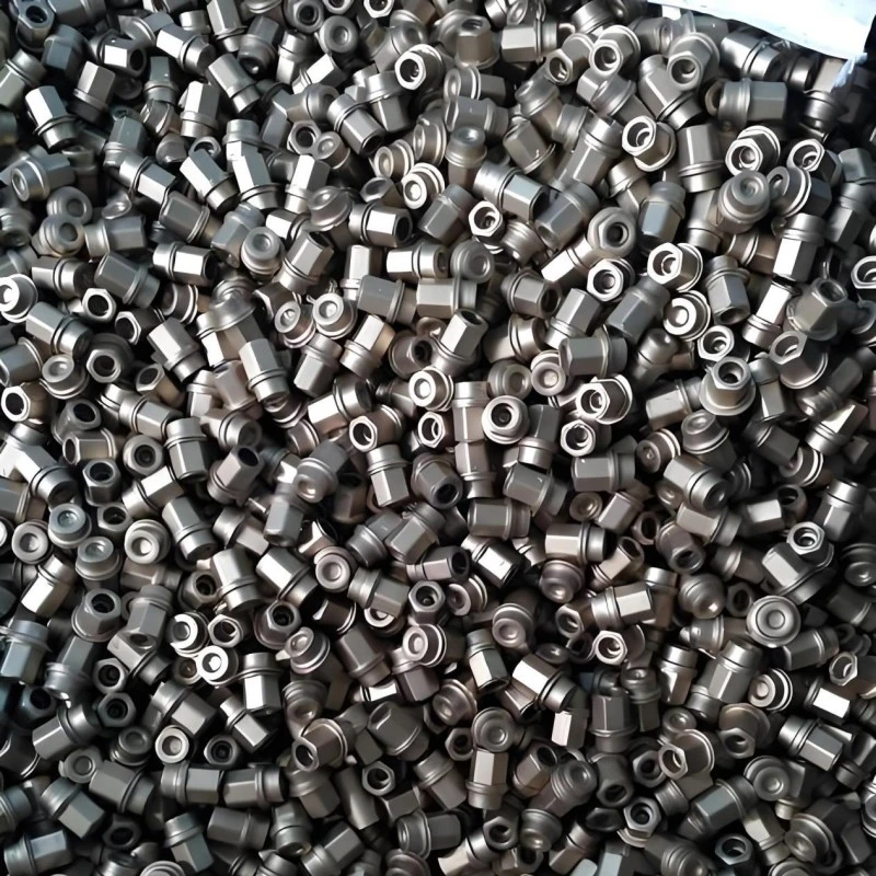
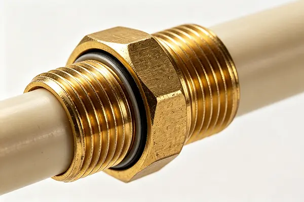
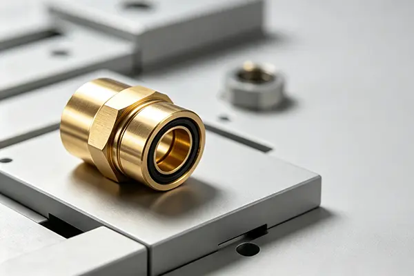
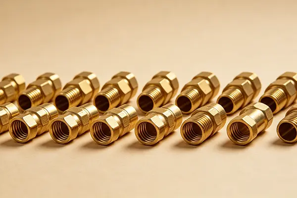
Our comprehensive product portfolio includes a wide range of brass rods (including low-lead and lead-free grades), brass fittings, and pipe components, engineered for exceptional mechanical strength, corrosion resistance, and machinability across plumbing, HVAC, automotive, and industrial applications.
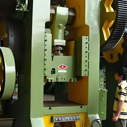
Copper CNC Machining Service
NINGXING provides Copper CNC Machining Service for electronics, telecommunications, power equipment, automotive, machinery, plumbing, and sanitary hardware applications. With more than 15 years of manufacturing experience, we work with copper and copper alloys for prototype development, small-batch production, and volume orders.
Our Copper CNC Machining Service is based on customer drawings, 3D models, and technical specifications. Copper bars, plates, tubes, and other forms can be processed according to component geometry, tolerance requirements, material grade, and application conditions.
NINGXING operates under an ISO9001:2015 certified quality management system, while applicable products meet CE and RoHS requirements. This provides international buyers with a documented quality framework for customized copper components.
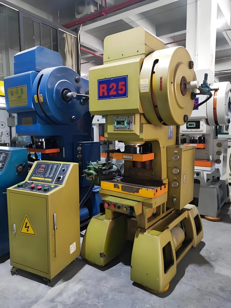
Copper Machining Technology
Controlling Common Copper Machining Problems
Copper has excellent electrical and thermal conductivity, but its softness and ductility make it more difficult to machine than many common engineering metals. Tool adhesion, burr formation, long chips, surface scratches, and deformation can affect both appearance and dimensional accuracy.
The machining strategy is therefore adjusted according to the copper grade and part structure. Cutting parameters, tool geometry, cooling conditions, and workholding methods are selected to reduce these risks during production.
Three-Axis to Five-Axis Processing
Three-axis, four-axis, and five-axis CNC machining centers are available for components with different structural requirements. CNC turning equipment is also used for cylindrical copper parts and turned components.
Five-axis machining can complete multiple surfaces in fewer setups, which is useful for complex connectors, irregular components, and parts with tight positional requirements.
Precision Control
Tolerance and Surface Finish: Standard machining tolerances can reach ±0.01 mm, while critical dimensions may be controlled to ±0.005 mm based on drawing requirements and part geometry.
Surface roughness can reach Ra 0.4 μm. For electrical contact surfaces, heat-transfer interfaces, and appearance-critical components, the finishing process can be selected according to the final application.
Dimensional Inspection
Quality inspection covers raw material verification, in-process measurements, and final inspection. CMM equipment, optical measuring instruments, and precision gauges are used for critical dimensions and geometric requirements.
Inspection requirements can be aligned with customer drawings, including dimensional tolerances, surface finish, hole dimensions, thread specifications, and other defined characteristics.
Manufacturing Process
Tooling and Cutting Parameters
Sharp carbide cutting tools and optimized cutting parameters are used for copper materials to reduce adhesion and improve surface quality.
Cooling and chip evacuation are also important during continuous machining. Appropriate coolant flow and machining parameters help control heat accumulation and prevent copper chips from interfering with the cutting process.
Workholding for Thin-Wall Parts
Copper components with thin walls or delicate structures can deform when excessive clamping or cutting forces are applied. Customized fixtures and soft-contact holding methods can be used to distribute clamping pressure and protect finished surfaces.
For demanding designs, DFM evaluation before production can identify potential deformation, tool-access, and tolerance issues.
Repeatability in Batch Production
For repeated orders, machining parameters and inspection standards can be documented to maintain consistency between production batches. This is particularly important for connectors, terminals, fittings, and other components requiring stable assembly dimensions.
Application Industries
New Energy Vehicle Connectors
A Ningbo-based new energy vehicle connector manufacturer previously experienced difficulties producing H65 brass conductive terminals. Tool adhesion, thin-wall deformation, and residual burrs caused the initial trial production yield to remain below 80%.
The machining process was improved through optimized cutting parameters, fixture adjustments, and changes to the finishing process. The production yield subsequently increased to more than 98%, allowing the customer to proceed with stable mass production.
Power Equipment Heat Dissipation
A power equipment manufacturer required high-precision copper heat sinks and busbars with strict requirements for surface finish and electrical conductivity.
C110 electrolytic copper was selected for the project, with the machining process adjusted to maintain consistent surface quality. The finished components achieved electrical conductivity of 100% IACS and met the customer's requirements for high-power operating conditions.
Copper Material Selection
Common Grades for CNC Processing
Material selection depends on conductivity, strength, corrosion resistance, machinability, and the intended application. Commonly requested grades include pure copper, brass, beryllium copper, tellurium copper, and free-cutting brass.
| Material Grade | Standard | Main Characteristics | Typical Applications |
|---|---|---|---|
| HPb58-3 | GB/T 5231 | Excellent machinability and suitable for automatic machining | Valves, pipe fittings, screws, nuts, gears |
| 59-1A | Industrial Grade | Good cutting performance and pressure processing capability | General structural components |
| C3604 | JIS H3250 | High strength and excellent machinability | Precision fasteners, valves, IT components |
| CW617N | EN 12164 | Good hot forging and machining performance | Faucets, valves, automotive parts |
| HPb59-1 | GB/T 5231 | Good machinability with balanced mechanical properties | Connectors, fittings, mechanical components |
| C37700 | ASTM B124M | Excellent hot working performance | Forged and pressed components |
| CW614N (CuZn39Pb3) | EN 12164 | Excellent cutting performance | Electronic connectors, valves, automotive parts |
| 62-1A | Industrial Grade | Suitable for copper bar machining | General copper components |
Selecting Copper for the Application
High-conductivity copper grades are generally considered when electrical or thermal performance is the primary requirement. Brass and other copper alloys can be more suitable when strength and machinability are more important.
For projects involving drinking-water or environmentally sensitive applications, the material specification should be confirmed before production to ensure compliance with the applicable requirements.
Machining Capability
Standard Processing Range
The following figures represent common machining capabilities. Actual limits depend on the component geometry, material, tolerance, tooling access, and production method.
| Parameter | Reference Capability |
|---|---|
| Maximum machining size | 200 × 80 × 100 mm |
| Minimum wall thickness | ≥0.8 mm |
| Standard tolerance | ±0.01 mm |
| Precision tolerance | ±0.005 mm |
| Surface roughness | Ra 0.4–1.6 μm |
| Minimum hole diameter | ≥0.5 mm |
| Thread size | M1.0 and above |
DFM Review for Complex Components
Thin-wall structures, deep cavities, small holes, and complex multi-sided features may require additional engineering evaluation. DFM review can be used to assess tool accessibility, clamping conditions, machining sequence, and achievable tolerances before production.
Larger dimensions or special structural requirements can be evaluated according to the individual drawing rather than being limited to the reference values above.
Surface Treatment Options
Finishing for Functional Surfaces
Copper CNC Machining Service can receive additional finishing when the application requires improved appearance, corrosion resistance, wear resistance, or electrical contact performance.
Available options include polishing, electropolishing, brushing, nickel plating, silver plating, gold plating, and other suitable surface treatments.
Plating Requirements for Electrical Parts
For connectors and conductive components, plating requirements should specify the functional contact areas, coating type, and thickness. This helps prevent unnecessary treatment on non-functional areas and protects critical surfaces during subsequent machining and assembly.
Frequently Asked Questions
What Is the Minimum Order Quantity?
MOQ depends on the component design, material, machining process, and order quantity. Prototype and low-volume orders can be accepted for design validation, while repeat production can be arranged for larger quantities.
What Copper Materials Can Be Machined?
Common options include C10100, C11000, C14500, C17200, C36000, T2 copper, and other copper alloys. The final material should be selected according to conductivity, strength, corrosion resistance, machinability, and application requirements.
What Surface Treatments Are Available?
Options include polishing, electropolishing, brushing, nickel plating, silver plating, gold plating, and other surface treatments suitable for copper and copper alloys.
For electrical components, contact surfaces and coating specifications should be clearly identified on the drawing.
How Is Copper Deformation Controlled?
Deformation is controlled through suitable cutting parameters, appropriate tooling, controlled clamping force, and fixture design. Thin-wall parts can also be reviewed during the DFM stage before machining.
What Is the Typical Lead Time?
Prototype orders generally require approximately 7–15 days after drawing and specification confirmation. Batch orders commonly require around 15–30 days, depending on quantity, complexity, material availability, surface treatment, and inspection requirements.
Urgent production schedules can be evaluated separately.
Can You Review Drawings Before Quotation?
Yes. CAD files such as PDF, DWG, STEP, and IGES can be submitted for engineering evaluation.
The review can cover material selection, tolerance requirements, machining accessibility, thin-wall structures, and other manufacturing considerations before quotation.
How Are Finished Parts Inspected?
Inspection includes incoming material verification, in-process dimensional checks, and final inspection. CMM equipment, optical measuring instruments, and precision gauges can be used according to the required inspection standard.
Can You Machine Complex Copper Components?
Yes. Three-axis, four-axis, and five-axis CNC equipment can be used for complex surfaces, deep cavities, multiple machining faces, and irregular structures.
The actual machining method is determined according to the drawing and tolerance requirements.
Request a Custom Quote
Send your copper component drawings or 3D files for manufacturing evaluation. The quotation can be prepared according to material grade, dimensions, tolerance, surface treatment, quantity, and delivery requirements.
Our Copper CNC Machining Service is suitable for buyers looking for a manufacturing partner for precision copper connectors, terminals, heat sinks, busbars, fittings, and other customized components.
Hot Tags: Copper CNC Machining Service, Custom Copper CNC Machining, Copper CNC Machining Parts
Send Inquiry
Contact Info
-
Address
No. 478, Daijia North Road, Industrial Zone, Changhe Town, Cixi City, Zhejiang Province, China
-
Tel
-
Email
Need brass rods or custom fittings? Send your drawings or samples today. ISO9001 certified, RoHS & PED compliant. Get a fast, professional quote from our expert team. Inquire now!